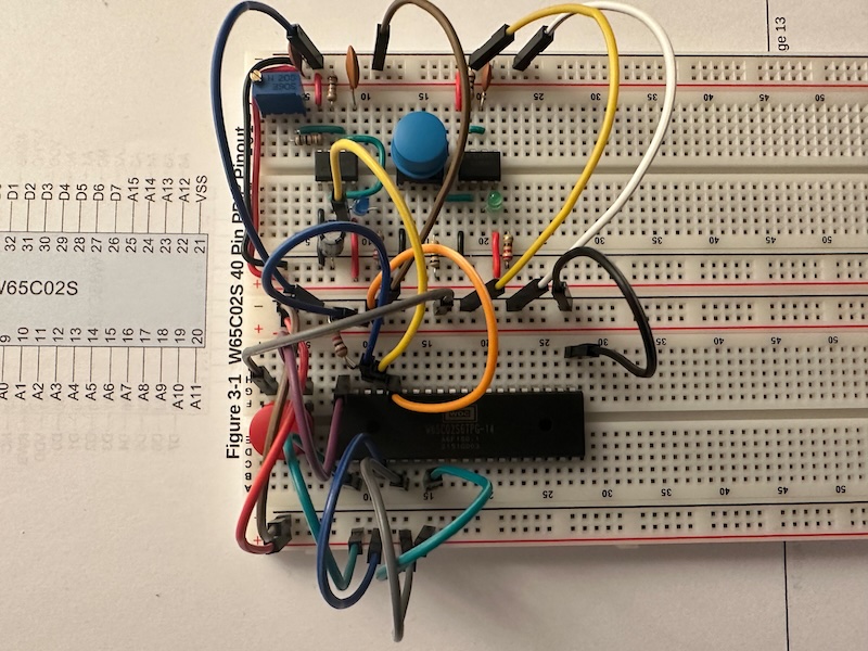
As the very first step to build up the actual Ben Eater 6502 breadboard computer is to connect and power the 6502 microprocessor. Just like Ben Eater, we also got the modern variant of the 6502, the 65C02S from Western Design Center (WDC). This time it was my son who came to my help: he took a new breadboard, and following the video he attached the microprocessor and connected all the pins that needed to be connected, including +5V (VDD), GND (VSS) and the clock (PHI2). This is not a complicated setup, but of course one cannot really see what the processor is doing.

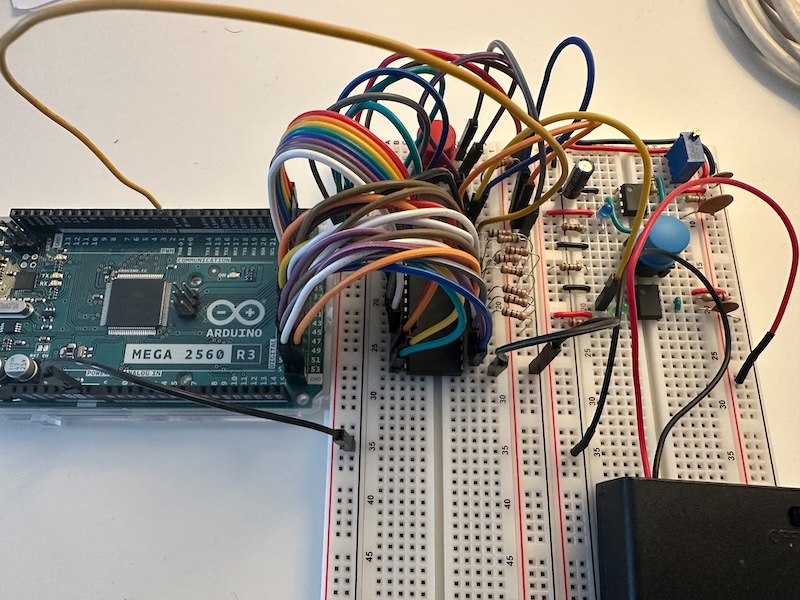
To see what’s going on, I took the Arduino and connected all the address pins (A0-A15) and data pins (D0-D7) of the 65C02S to the extra digital IO ports of the Arduino.

With a small piece of SW as show in the video I could quickly see what was happening on the address and data buses. I mean almost… somehow the result didn’t match the one that Ben Eater got, but I quickly realized the root cause: he connected A15 through A0 to the even Ardunio ports 22-52, while I connected A0 thought A15. That is in the opposite order. But a quick change in the code fixed it. The final step was to add some resistors to connect the data pins and to hardcode the value 0xAE, so the output on the serial line was then just as expected:

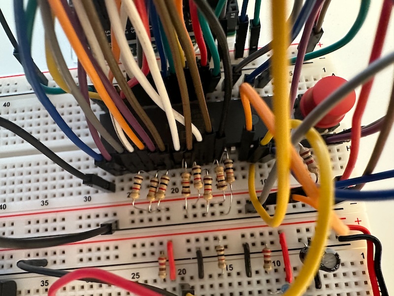
To hardcode the value, you take the binary value 10101110, and connect D7 through D0 with 1k resistors to +5V (1) or to GND (0). You can really read it off from the legs of the resistors as you can see the picture below. My daughter liked it so much that together we calculated how to change the configuration so that it shows 0x2A, because she is in class 2A 🙂
