It is nice to have a microprocessor that executes hard-wired NOPs, but if you want to do something more complicated then it is useful to have some kind of memory, for example a ROM. This is what also Ben Eater’s second video introduces for his breadboard computer. I already had an 32kByte EEPROM chip, just needed a programmer. And if you are building a breadboard computer and your wife understands what an EEPROM programmer is, then you can call yourself lucky. And if she buys you one then even luckier. :-*
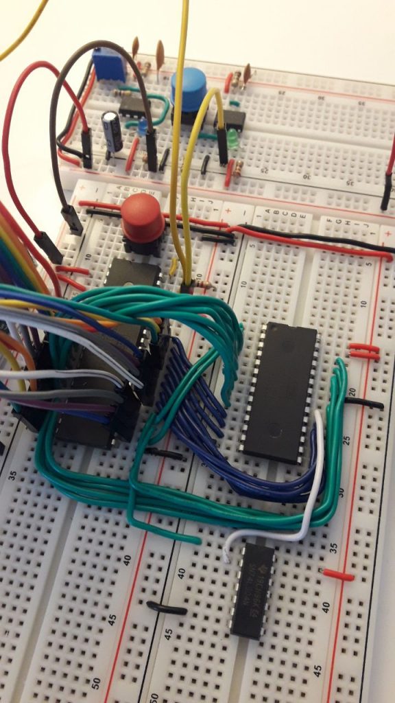
Connecting the EEPROM to the W65C02S is straightforward, you just have to look at the pinout carefully. The 6502 has the address bits on the “left” side top-down from A0 to A11, and on the “right” side bottom-up A12-15, and then the data bits from D7 down to D0. The AT28C256 on the “left” side starts on the top with A14, then A12 and then A7 down to A0. Then it has tree data bits D0 (aka I/O0) to D2 (I/O2). On the “right” side from the bottom D3 (I/O3) to D7 (I/O7), then chip enable, A10, output enable, A11, A9, A8 and A13. You can see in the picture below that the wires are a bit messy.

By the way, I have decided to use a different layout than Ben Eater: I plan to put the ROM and RAM chips to a breadboard above the CPU board, and later on the Versatile Interface Adapter (VIA) beside the CPU.
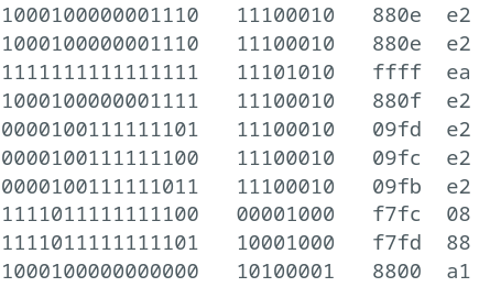
After putting in the wires, I have connected the arduino in place of the EEPROM to see if the wiring was correct. Afterwards I created the ROM image used by Ben Eater flashed on the EEPROM, inserted into its place. AAaaaand…. it almost worked. You can see the first 10 clock cycles below, 7 steps for reset, 2 for the read of the starting address and the last one is reading the first instruction.

Reading the start address (reset vector) always happens from addresses 0xfffc and 0xfffd, so that’s where you can identify if something is wrong. As you see, somehow address bit nr. 11 was 0 instead of 1. But somehow the data has been read, although some bits were flipped there too. Anyway, first I looked at pin A11, it is easy to find, at the lower left corner of the CPU. I used colored jumper wires, they are in the sequence of red, orange, yellow, green, blue, purple, grey and white. A0 is red, A1 is orange, etc, and then A8 is red again, A9 is orange and so on. On the Arduino I used one row of the extra digital pins (22, 24, 26, … 52). Then the data pins are again D0 is red, D2 is orange, etc and on the Arduino they are in the other row of the additional pins, but only the upper eight (39, 41, 43, … 53).
And as it turned out, I mixed up two green wires! 44 went to D3 and 45 went to A12. This swap is best visible on these two lines, when fffc/00 is expected but f7fc/08 is shown. But, the good thing is that the board itself was ok, just the arduino was connected on the wrong way. After swapping back these two wires, everything was working as expected.
Small remark regarding minicom: if you use Debian, just download the source from git, build, create a .deb package and install. And it works.