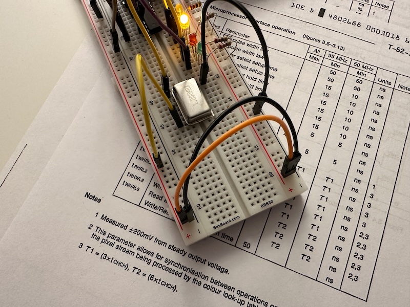
Yesterday I was unable to solve the issue with the RAMDAC not setting the color value register, so I gave up, and decided to make an entry about the progress so far. But I was so tired that I decided to do it this morning, making use of the public holiday. I was watching enough videos from Ben Eater by now to start suspecting the timing. Especially when I was trying to connect my clock module and sporadically the results randomly changed.
Today morning with fresh head, after creating the blog entry, I looked again into the G171 specification (as of today available for example here, or as part of the INMOS Graphics Databook here), and looked at the timings. The only difference I could see between the address register and the color value register was the minimal delay between address / color write and next read. For the address register it is tWHRL3, for the color value register it is tWHRL2. Timing between color value writes is tWHRL1. For tWHRL1 the minimum is defined as τ1, for tWHRL2 as well as for tWHRL3 it is τ2, where τ1=3 x tCHCH and τ2=6 x tCHCH. The value tCHCH is the time between two consecutive raising edges of the clock.
I decided to print out the data sheet, because I can think better if I can have it in my hand and make notes or drawings. But before looking into the papers I made some thoughts how I can insert a clock signal. First I was planning to use the Arduino, but I was not sure how to synchronize it with the other operations, and also I wasn’t sure if it was fast enough. Also I was not confident that my 555 based clock module can provide the right signal. And even though for most of the timings there are only minima and no maxima, the clock, that is tCHCH has a maximum: 10000ns. Note that the usual values are 28/20 for this chip, as it runs 35/50Mhz.
But, I happen to have two 1MHz quartz oscillators for the BE6502 project, and 1MHz means tCHCH of 1000ns, well within the range. And I expect it to be more stable than a SW clock from an Arduino. So I hooked up the oscillator, and connected it directly to pin with the lucky number 13, and tada… all read and write operations were working as expected.

The data sheet does not explicitly describe this behavior, but it mentions that to enable independent access for the pixel interface and the microprocessor interface, the G171 internally synchronizes memory writes to the pixel clock.
Now the first step with the RAMDAC is done, I can move to the CRTC, but that is another story.