Building the BE6502 computer – the microprocessor
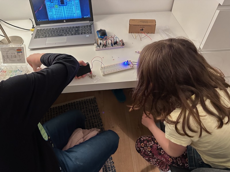
As the very first step to build up the actual Ben Eater 6502 breadboard computer is to connect and power the 6502 microprocessor. Just like Ben Eater, we also got the modern variant of the 6502, the 65C02S from Western Design Center (WDC). This time it was my son who came to my help: he took a new breadboard, and following the video he attached the microprocessor and connected all the pins that needed to be connected, including +5V (VDD), GND (VSS) and the clock (PHI2). This is not a complicated setup, but of course one cannot really see what the processor is doing.
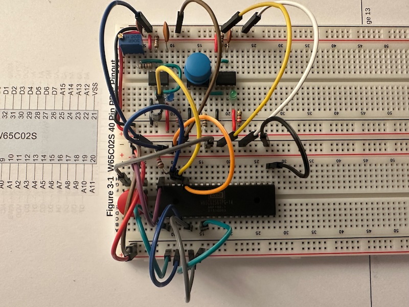
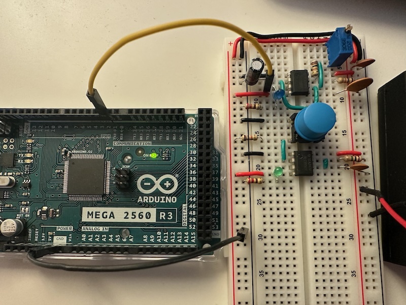
To see what’s going on, I took the Arduino and connected all the address pins (A0-A15) and data pins (D0-D7) of the 65C02S to the extra digital IO ports of the Arduino.
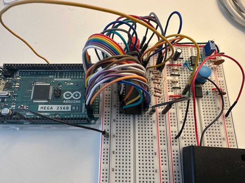
With a small piece of SW as show in the video I could quickly see what was happening on the address and data buses. I mean almost… somehow the result didn’t match the one that Ben Eater got, but I quickly realized the root cause: he connected A15 through A0 to the even Ardunio ports 22-52, while I connected A0 thought A15. That is in the opposite order. But a quick change in the code fixed it. The final step was to add some resistors to connect the data pins and to hardcode the value 0xAE, so the output on the serial line was then just as expected:
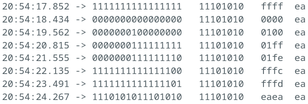
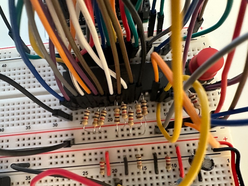
To hardcode the value, you take the binary value 10101110, and connect D7 through D0 with 1k resistors to +5V (1) or to GND (0). You can really read it off from the legs of the resistors as you can see the picture below. My daughter liked it so much that together we calculated how to change the configuration so that it shows 0x2A, because she is in class 2A 🙂
Testing the Arduino
I already wanted to get an Arduino to do some experiments, but the final push was seeing Ben Eater using an Ardino Mega do do some debugging on his 6502 computer. Now that we have built up the astable and monostable timers and the Arduino also arrived it was time to test it.
The setup I used is quite simple: connect GND to the common ground, and pin 2 to the clock signal from the breadboard and then hook up an interrupt with pin 2 that prints out something. For the HW setup just two jumper wires are needed.
And the SW isn’t too complicated either.
#define CLOCK 2

unsigned int pushed;
unsigned long lasttime;

void setup() {
  Serial.begin(57600);
  Serial.println("Hello World");

  pushed = 0;

  pinMode(CLOCK, INPUT);
  attachInterrupt(digitalPinToInterrupt(CLOCK), onClock, RISING);

  lasttime = millis();
}

void onClock() {
  unsigned long time = millis();
  unsigned long delta = time-lasttime;
  lasttime = time;

  pushed = pushed + 1;

  Serial.print(delta);
  Serial.print("  You have pushed a button ");
  Serial.print(pushed);
  Serial.println(" times.");
}

void loop() {
  // put your main code here, to run repeatedly:
}Monostable timer
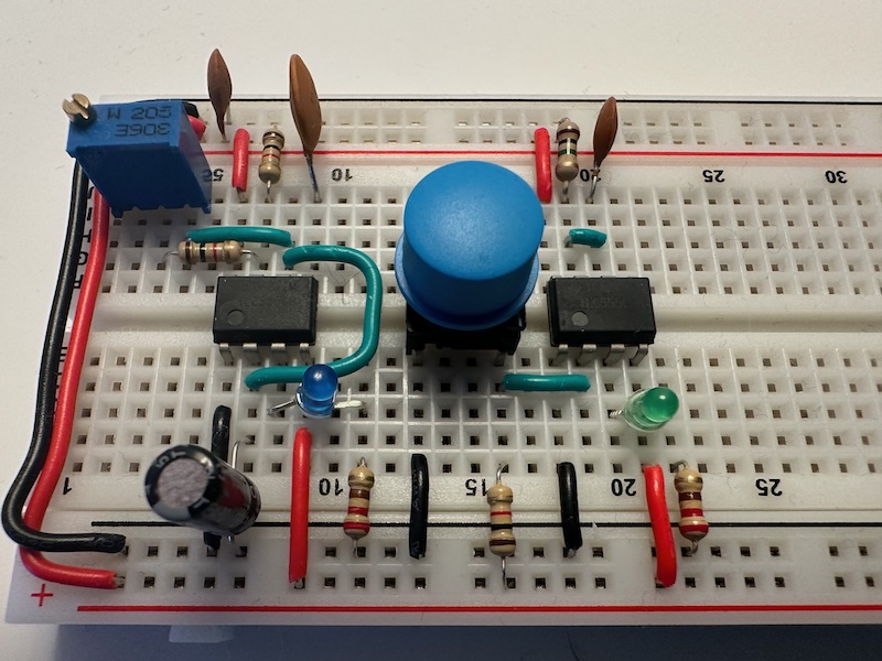
Now that we have all the components, we have quickly built up the monostable time based on Ben Eater’s video. This time we build it up with my daughter, and Ludovicus the Lion also helped.
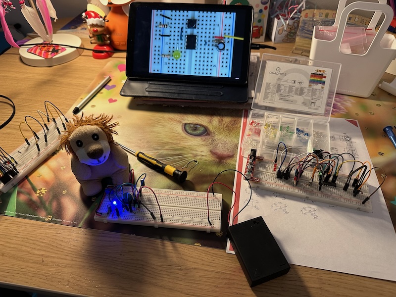
After the first prototype with jumper wires I have also cleaned up the board. On the picture you can also see the astable part that we cleaned up last time.
New package arrived
Finally I have managed to order some missing components for the Ben Eater 6502 breadboard computer.

Most importantly I have ordered a WDC 65C02, the newest CMOS version of the original MOS 6502 CPU. I have also ordered some tactile switches (push buttons). The old one was not stable enough and I have found the APEC MUTLIMEC 5G, which is quite robust, available in a through hole configuration, and the pins have a distance that is multiple of 0.1 inch, so they can be plugged into a breadboard. More precisely, the distance is 0.3 inches (7.62 mm), which is 0.1 inch (1 hole) bigger than some others I have seen in videos, but these are the ones that I could find in an online shop. The positive thing is that you can get nice button caps for them. I wish I could find some similar latching pushbutton or toggle swiches.
Two SRAMs, an EEPROM and a Versatile Interface Adapter (VIA) as well as an RS232 interface chip were in the package as well.
To be able to program and debug the setup I have also ordered an Arduino MEGA, with its 54 digital inputs I should be able to follow Ben Eater’s approach and see what’s happening on the various buses. And I can also experiment with other things using the Arduino. And I also ordered an Arduino Nano Every with headers. I just find it fascinating to have such a little board. And with the headers I can directly plug it into a breadboard.
Last, but not least, I have also ordered an LCD display. It was difficult to find one with direct interface to the controller chip. Most of them have a built-in SPI adaptor, so that it can be easily connected to a RPi or Arduino board without having to program the registers. But that’s not what I want to do.
Read MoreCleaning up the breadboard
Due to work and school we do not have much time for the electronics project, but we managed to get some wires and tools.
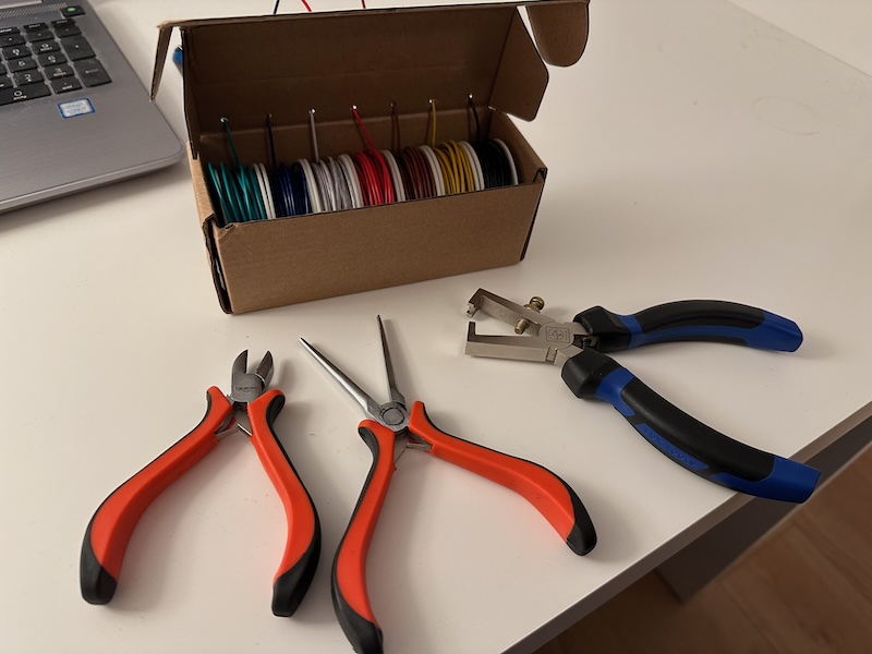
The wires have the size 22 AWG, where AWG stands for American Wire Gauge. You can look up in the internet what sizes there are and what they mean in mm2. It took some time to find solid wires because sometimes it is not clear from the description if it is solid or stranded and the pictures often make things even more confusing. At the end I found the Haerkn Electric Wire Kit 22 AWG, solid, 7 colors. Product number B08BZKM7R5. So far I’m satisfied with it.
I got the tools from a local hardware store. Not the cheapest ones, but also not too fancy. I could not find a good stripper that also fits 22 AWG, so we got one that is adjustable with a help of a screw. Not perfect, but does its job. And here is a sentence I never thought I would tell to my son: “we are not going to give out 100 euro for a fancy stripper“. 😀
For hints and ideas we again turned to Ben Eater and his video, Breadboarding tips.
Both the kids were happy to help.
So far we managed to build up the astable 555 timer again, this time with fitting wires and tightly packed components. Unfortunately I forgot to take a picture of the board when it was finished, but you’ll see how it looks in the next post when we added the monostable timer.
Read MoreIVAO